operanthouseのヘッダー
Kitaya lab
Electronic circuit production #1
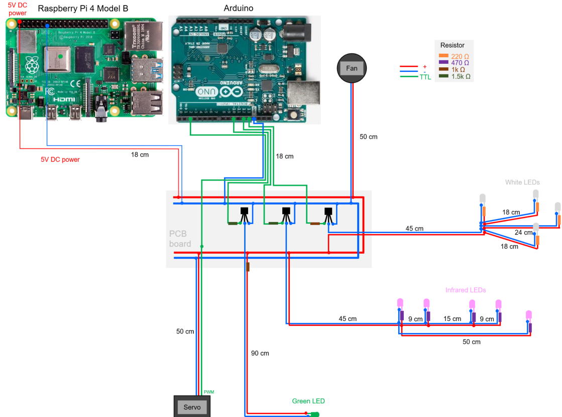
This schematic illustrate the circuitry of the switching board used to control LEDs and a servo motor.
Let's start making the PCB board circuit shown below.

Soldering of the registers
Prepare solder, soldering iron, PCB borad (bread board layout), 1kΩ and 1.5kΩ registors.


Solder the registers as shown.

<the other side>

Remove the excess leads.

Soldering of the transistors
Bned emitter lead as illustrated.

Solder the transistors onto the PCB as shown in the pictures.


Soldering of White LEDs (for roof illumination)
Next, solder the wires to the white LEDs and PCB board.

Prepare electric wire.

<If you do not have a stripper>
Make 2 notches on both sides of the vinyl film with the tip of the nippers.

Peel of the vinyl film to expose the wires inside.

<If using a stripper>
Place the wire on the blade of the stripper.

Close the blades tightly and pull the vinyl film off.

Make sure not to cut the electric wires inside.

Cut wires to the following lengths.
18cm x4, 24cm x2, 45cm x2

Next step is soldering of the the LED shown below..

Twist a 220Ω resistor to the anode lead (longer one) of the LED for temporary fixation and solder it.


Then solder the prepared wires to the opposite lead of the resistor.

Solder other wires to the cathode.

Cover the exposed joints with heat-shrink tubing. Apply heat (e.g., using the soldering iron's shaft or heat gun) to shrink and secure the insulation.


Before the soldering, slide the 3 mm heat-shrink tubing onto the wires.

Solder 220Ω registers to white LEDs. Solder 18 or 24 cm wires to the opposite lead of the resisters and cover with heat-shrink tubing.


Solder the 45 cm wires to the PCB board as shown below.

Soldering the Power Cables
Prepare jumper wires with female connector. Cut off the unnecessary male connector at the end of the wire.


Solder the cables to the PCB board.

If your wiring is correct, the circuit should appear like this.
