operanthouseのヘッダー
Kitaya lab
Electronic circuit production #2
Soldering of infrared LEDs
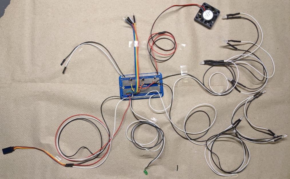
Next let's solder IR LEDs onto the circuit board.

Prepare the specified lengths of wires and five IR LEDs soldered with a 470Ω register.
9cm x4, 15cm x2, 45cm x2, 50cm x2


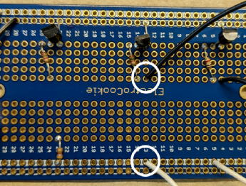
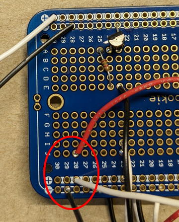
Solder the LED in the red square as shown below.
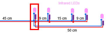

Place the heat-shrink tubing.

Solder the other LED.


↓

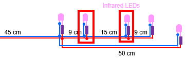
Solder the last two LEDs. Heat-shrink tubing cannot be applied after soldering of these LEDs so ensure the tubing is in place before the soldering.
↓


↓

Solder the 45 cm wires to the board.
Soldering of the Cue LED
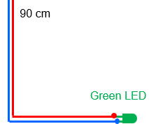
Solder a green LED to 90cm wires.
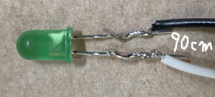
Bend the LED leads to approximately 80 degree.

Cover the leads and exposed wires with epoxy adhesive to provide waterproofing and mechanical reinforcement.

Solder the wires to the board as shown the below.

Soldering of Servo Cable

Remove the male connector from the servo cable. If the length is shorter than 50 cm, extend it appropriately.
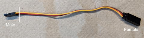
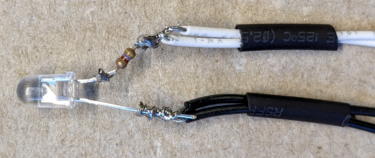
The below is an example of cable extension. If you want to know how to extend the electronic wire, see Tips to extend wires.
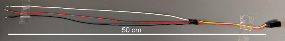
Solder the extended servo cable wire to the board. In the example shown, black = ground, white = 5V, red = PWM control signal. Check manufacturer's manual or website to determine which color represent which line.
If the borad contains separate power rails, bridge them with solder to supply power to both rails.

Soldering of Arduino Connection Wires
Prepare five jumper wires with male connectors.
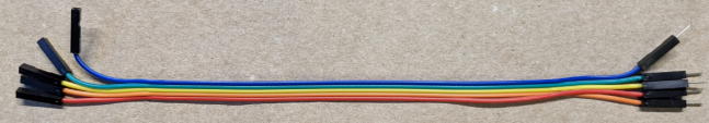
Remove unnecessary connectors.

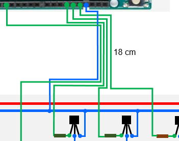
Solder each jumper wire to its corresponding line on the board as shown below.

Soldering of Ventilation Fan

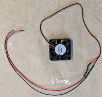
Prepare 4cm ventilation fan.
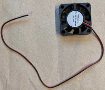
If the length is less than 50 cm, extend it.
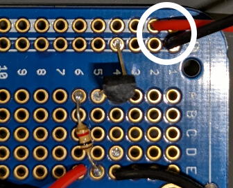
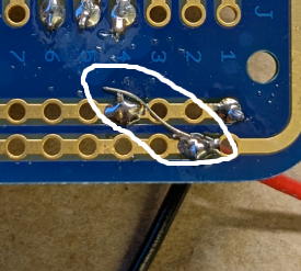
Solder the fan wires to the power rails of the board.
Finally, inspect the underside of the board for any untrimmed leads, loose solder or fragment of wire.
Once all insulation is verified, the wiring process is complete.